Learning Hardware with KIM-1
This post will probably be highly unorganized and probably hard to read because I’m only sharing notes and thoughts for myself, putting down whatever I’m thinking.
Background
It’s always been a shame, a flaw, that my university decided to isolate the College of Computer Science, while putting Electrical and Computer Engineering in another college, so that CS kids are restricted from touching circuits and electronics, while engineers don’t get to learn algorithms. Recently I snuck into a hardware class at my uni’s ECE department, and I am even more annoyed by this problem. Anyways, we are currently learning hands-on hardware programming and circuit building with the 6502 microprocessor using the KIM-1 (Keyboard Input Monitor).
Wait - let me write this in a serious way. Materials used:
- KIM-1
- Microcomputer Experimentation with the MOS Technology KIM-1 by Lance A. Leventhal (The Blue Book)
- The Pink Sheet
- 6502 Assembly Language Programming by Lance A. Leventhal (The Orange Book)
- bread board
- Resistors
- Wires, lots of wires
- 5V power supply
- …
Progress Update
Lab 2
02-11-2025 update
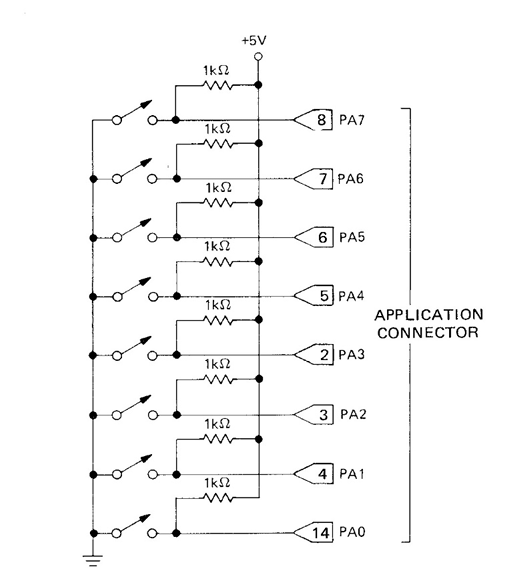
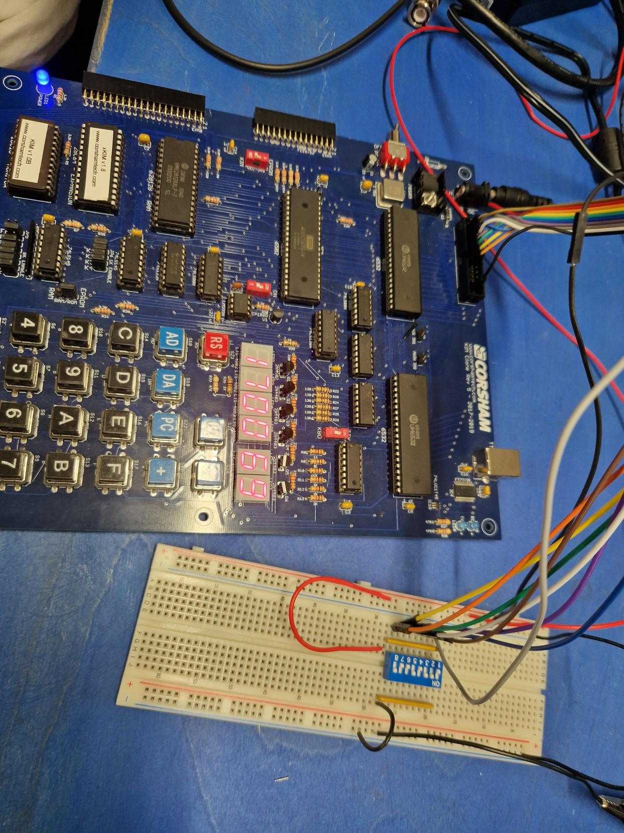
So far, I’ve read through and finished Lab 0 and Lab 1 in the Blue Book. Today I started with Lab 2. I’ve built the circuit for simple input with 8 switches representing 8 bits.
This is how it looks IRL:
02-16-2025 update
I learned how to use flags to achieve logical branch, thus creating a loop for the program. For example, below is a program that returns controll to the monitor when switch 6 is closed (see circuit image above):
memory@     Contents(Hex)               Instruction (Mnemonic)
0200		AD		        SWITCH6	    LDA	$1700
0201		00
0202		17
0203		29					        AND	#%01000000
0204		40
0205		D0					        BNE	SWITCH6
0206		F9
0207		00					        BRK
Short explanation:
- Load from address $1700 (input port) to accumulator.
- Perform AND with 01000000 (40 in hex).
- Branch if not equal: if Z=0, jump -7 memory locations (F9 in hex) to the start of the program; if Z=1, break. // When a switch is closed it signifies a logic 0, when it’s open it signifies a logic 1. Therefore, when switch 6 is closed while others open, the accumulator reads 10111111(DF) from $1700. Since the AND operation produces 0 (DF AND 40 = 0), the Zero flag would be true (Z=1), the program breaks from the loop.
However, I ran into some unexpected problems when trying to do PROBELM 2-9 in the Blue Book, which is using BIT and BVS to break the program from the loop. Below is the final program that works:
0040        40
0200        A5      LDA
0201        40
0202        2C      BIT
0203        00
0204        17
0205        70      BVS
0206        F9
0207        00      BRK
As you can see, it loads from $40 and performs AND with $1700 using BIT which results in the overflow (bit 6) flag V=0 when switch 6 is closed, hence breaking the loop.
However, it is weird that when I load $1700 first, and BIT that with $40, the program never breaks from the loop. The problem now still remains unresolved, I’ve been troubled by that for a long time… Anyways, at least I have one version that works.
02-17-2025 update
Just finished Lab 2. Below are some example programs
0200	AD	LDA
0201	00
0202	17
0203	C9	CMP
0204	DB
0205	D0	BNE
0206	F9
0207	AD	LDA
0208	00
0209	17
020A	C9	CMP
020B	7E
020C	D0	BNE
020D	F9
020E	00	BRK
This program waits for swiches 2 and 5 to be closed at the same time and then for switches 0 and 7 to be closed at the same time. The way it works is using CMP (compare), instead of comparing by bit, this operation compares by a whole byte (the hexadecimal), therefore it would only return 0 if the exact switches are closed.
Here is a program (longest program in Lab 2) that waits for either switch 2 to be closed followed by switch 5 or switch 5 followed by switch 2, only one at a time
0200	AD	LDA
0201	00
0202	17
0203	C9	CMP
0204	DF
0205	F0	BEQ
0206	04
0207	C9	CMP
0208	FB
0209	D0	BNE
020A	F5
020B	AD	LDA
020C	00
020D	17
020E	C9	CMP
020F	DB
0210	D0	BNE
0211	EE
0212	00	BRK